
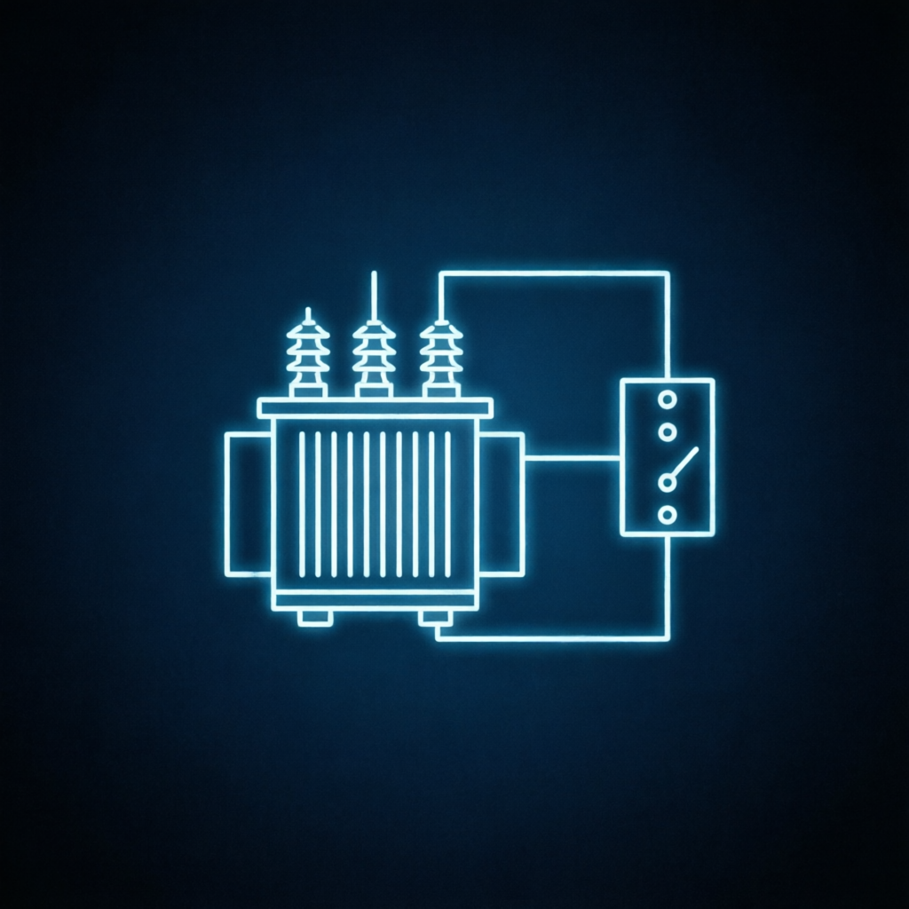
Electrical Power Management System
Complete electrical system coverage from medium voltage to end-user distribution, with real-time monitoring and energy optimization.
End-to-end power visibility that turns energy data into measurable savings.
EPMS covers the full power chain from medium voltage through LV distribution to end-user panels, visualized on single-line diagrams with real-time status.
Energy flow tracking, UPS battery health, generator sets and ATS transfer control sit on the same point database, so power events and energy performance can be read together.
7 Subsystems Inside EPMS
Primary System Diagram
Single-line diagram visualization with real-time status.
Energy Flow
Comprehensive energy flow tracking and optimization.
Medium Voltage
MV distribution monitoring and protection coordination.
Power Distribution
LV distribution panel monitoring and load balancing.
UPS Management
UPS status, battery health, and runtime estimation.
Generator Sets
Generator monitoring with automatic transfer switch control.
Network Topology
Electrical network topology visualization.
EPMS Technical Parameters
Platform Baseline
Every system runs on the IntelliOne platform base, so platform-level redundancy supports all five systems and their shared modules uniformly.
Values marked as design standard are engineering targets; 350 MW+ operating load reflects successfully delivered projects.
Redundancy Design in EPMS
System-Level Redundancy
Dual controllers and dual communication links back up power monitoring and control loops, so protection logic keeps running through a single controller failure.
Dual-Controller Redundant Architecture
Power monitoring and control run on two controllers with dual communication links backing each other.
Double-Backed Control Loops
Distribution monitoring and control loops are duplicated, so a single controller failure does not interrupt power monitoring or protection logic.
Isolated Fault Domain
A fault inside this system is contained by its own redundancy design and does not spread to other modules running on the platform.
Power monitoring stays online
Each system is independently highly available: a single system fault is isolated and does not spread to other modules.
Platform Base Support
Level 1 · IntelliOne unified platform layer
Every system runs on the IntelliOne platform base, so platform-level redundancy supports all five systems and their shared modules uniformly. Dual-node hot-standby cluster, multi-copy data storage and dual communication links remove platform-level single points of failure, keeping the global management view continuously available.
Deployment-Level Redundancy
Level 3 · Engineering delivery standard
Hardware-Level Redundancy
All control hardware, gateways and core servers use industrial dual-power redundant configuration, so a single supply failure does not affect device operation.
Network-Level Redundancy
Dual physical network links are deployed, with management and control networks physically separated and each carrying its own redundant paths.
Power-Level Redundancy
Critical control nodes include UPS backup as standard, so monitoring, emergency control and data reporting continue during a power loss.
Standard delivery configuration on every project — not an optional add-on. No single point of failure on site, suited to complex grid and environmental conditions across Southeast Asia.
Other Systems & Modules on IntelliOne
See EPMS in the Live Console
Explore monitoring, alarms and optimization flows with real-time console access.